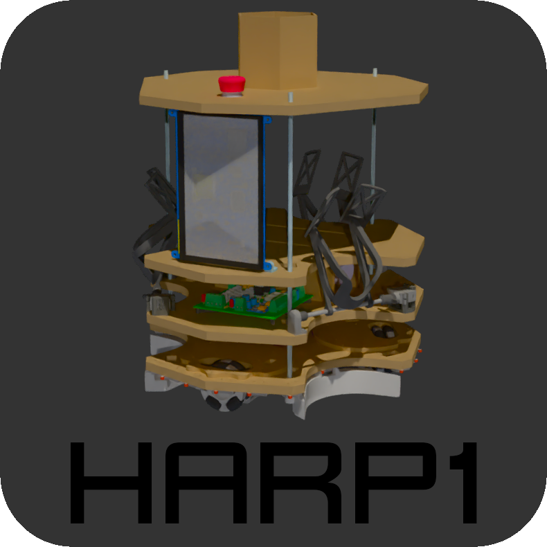
Principle: HARP1 was designed to efficiently collect "cakes" from the game field and deliver them to specific storage zones. It also featured a mechanism that allowed it to "change appearance" at the end of the match to showcase during competition.
- 3 Nema 17 stepper motors (59Ncm) for propulsion
- Li-Po 14.8V 8400mAh battery
- 1 Arduino Nano V3 microcontroller and 1 Raspberry Pi 3B+ connected via USB
- Chassis made of 3mm threaded rods and laser-cut MDF
- 3D-printed mechanical parts
- 2D LiDAR for obstacle detection
Overview diagram
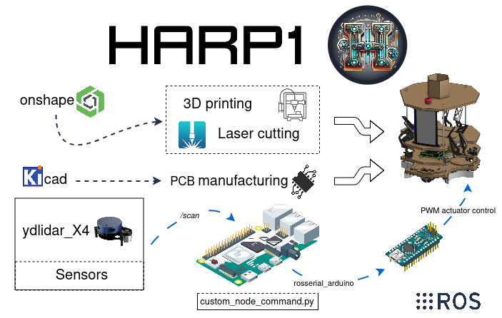
Workflow and components of the robot HARP1 (Holonomic Autonomous Robotic Platform 1)
Mechanics
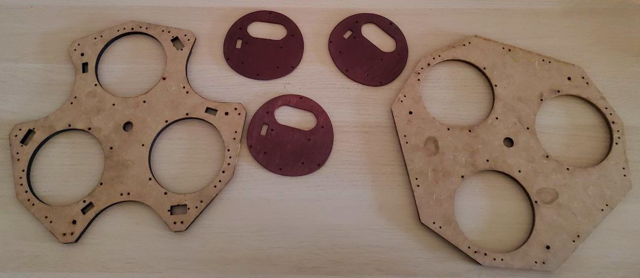
This robot was designed using Onshape, a CAD software. Its structure consists of 5mm laser-cut MDF layers and assembled using 3mm threaded rods. Additional components are crafted from 3D-printed PLA, ensuring lightweight and customizable elements. The overall dimensions strictly adhere to the regulations of the French Robotics Cup.
Electronics
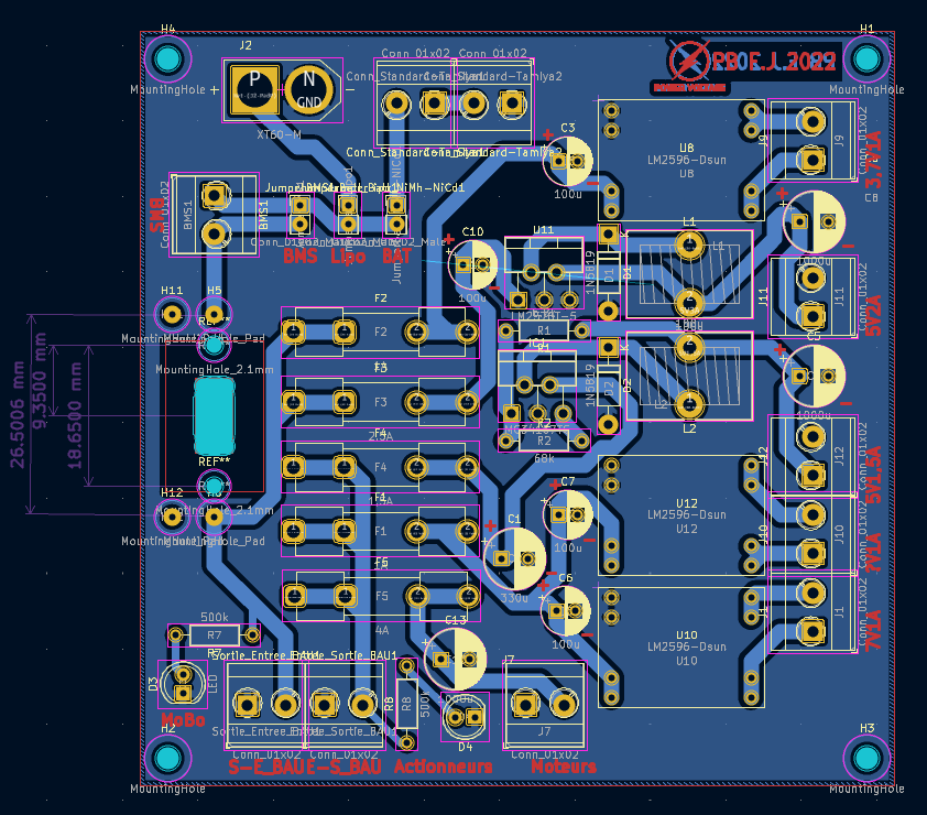
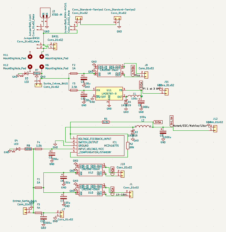
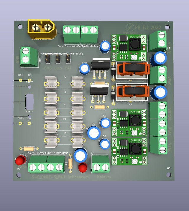
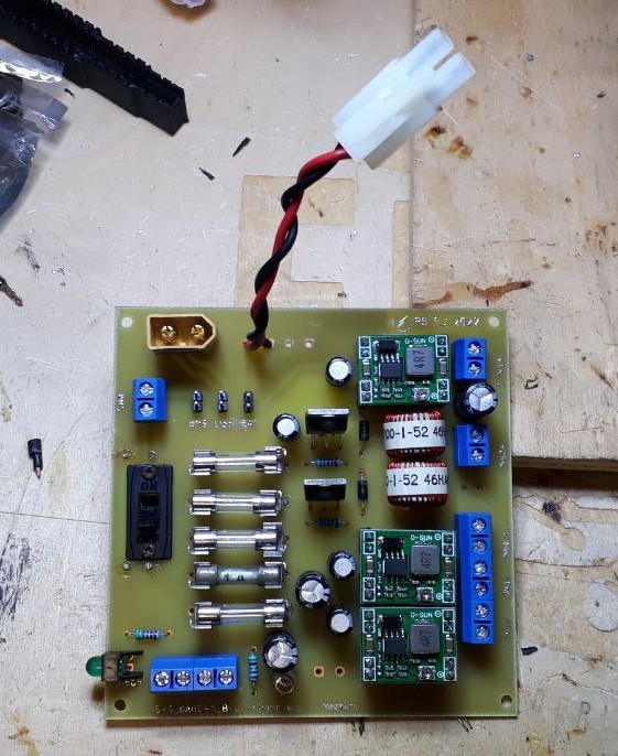
The power board plays a crucial role in distributing power from the battery to various modules while adapting the electrical parameters as needed. It was designed using KiCad, an open-source software for printed circuit board (PCB) design. Following the validation, the PCB was manufactured. In addition to onboard protections, such as fuses, short-circuit protection, and thermal safeguards, a low-voltage buzzer alarm was added to the battery to enhance its protection.
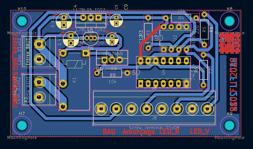
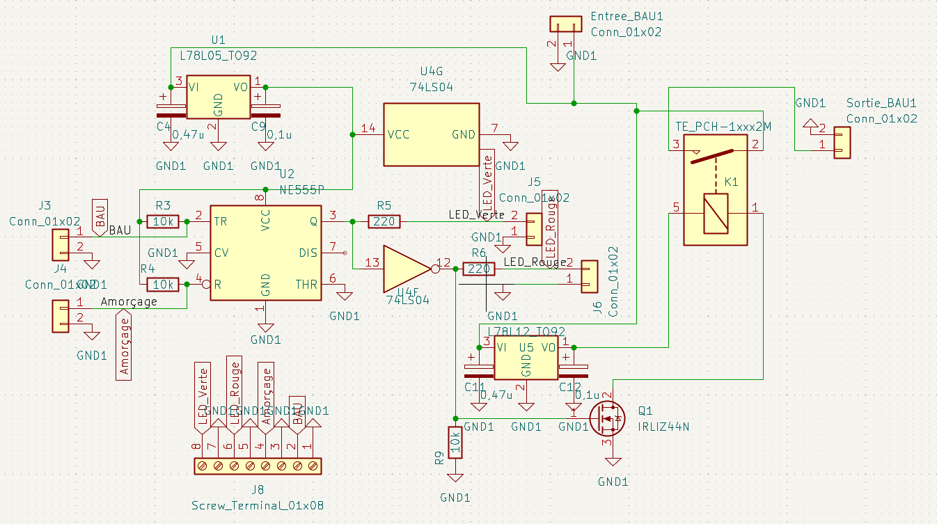
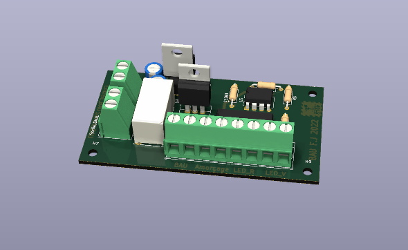
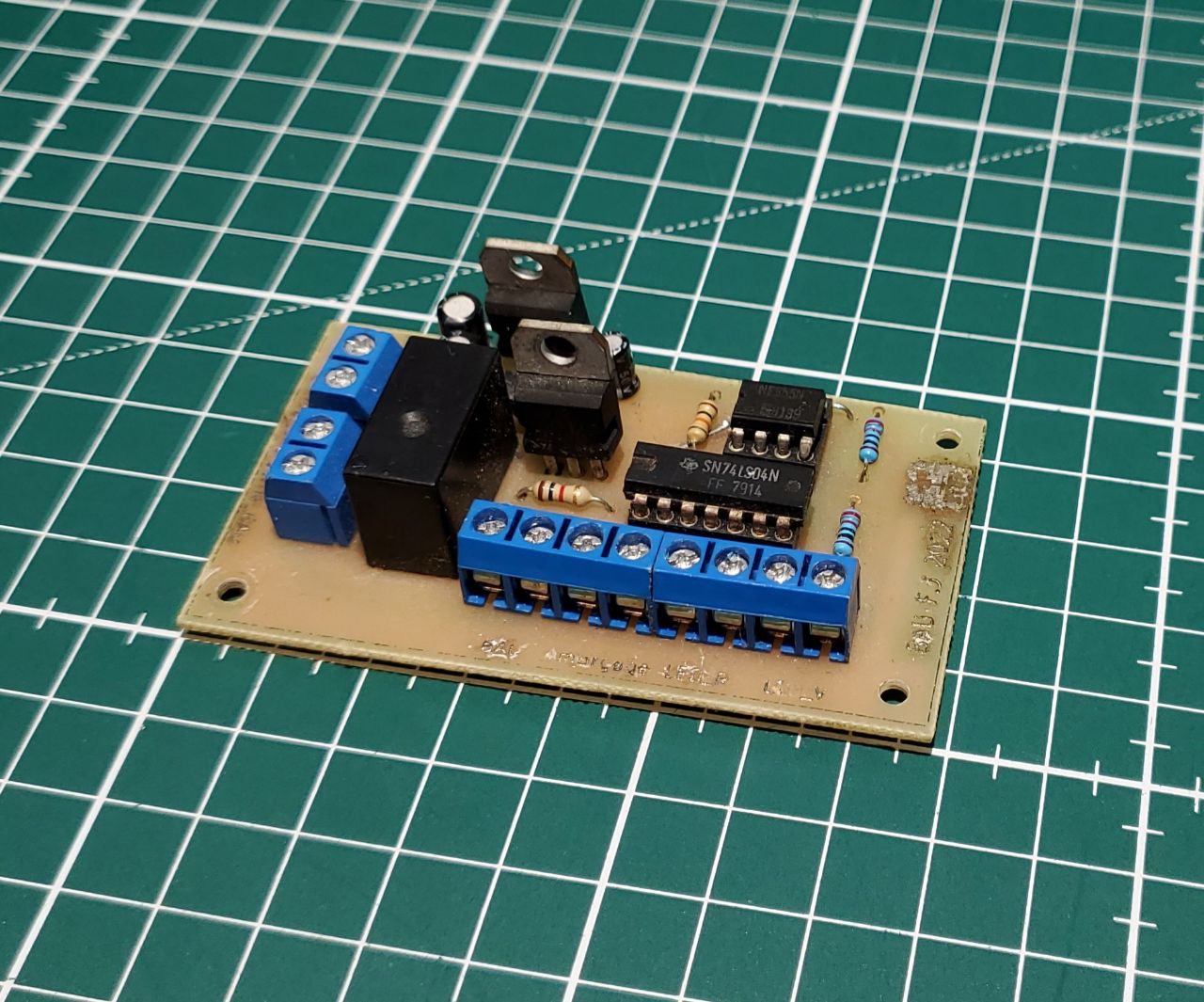
The Emergency Stop Button Board ensures the safe operation of the system by integrating a relay controlled by two push buttons. One button serves as the activation switch to power on the system, while the other functions as an emergency stop button, immediately cutting off power when pressed. This board is a critical safety feature, providing a reliable and straightforward way to quickly halt the system in case of unexpected issues. Its design prioritizes simplicity and robustness, ensuring it meets high safety standards.
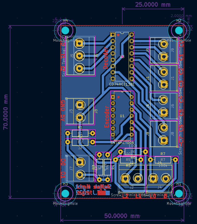
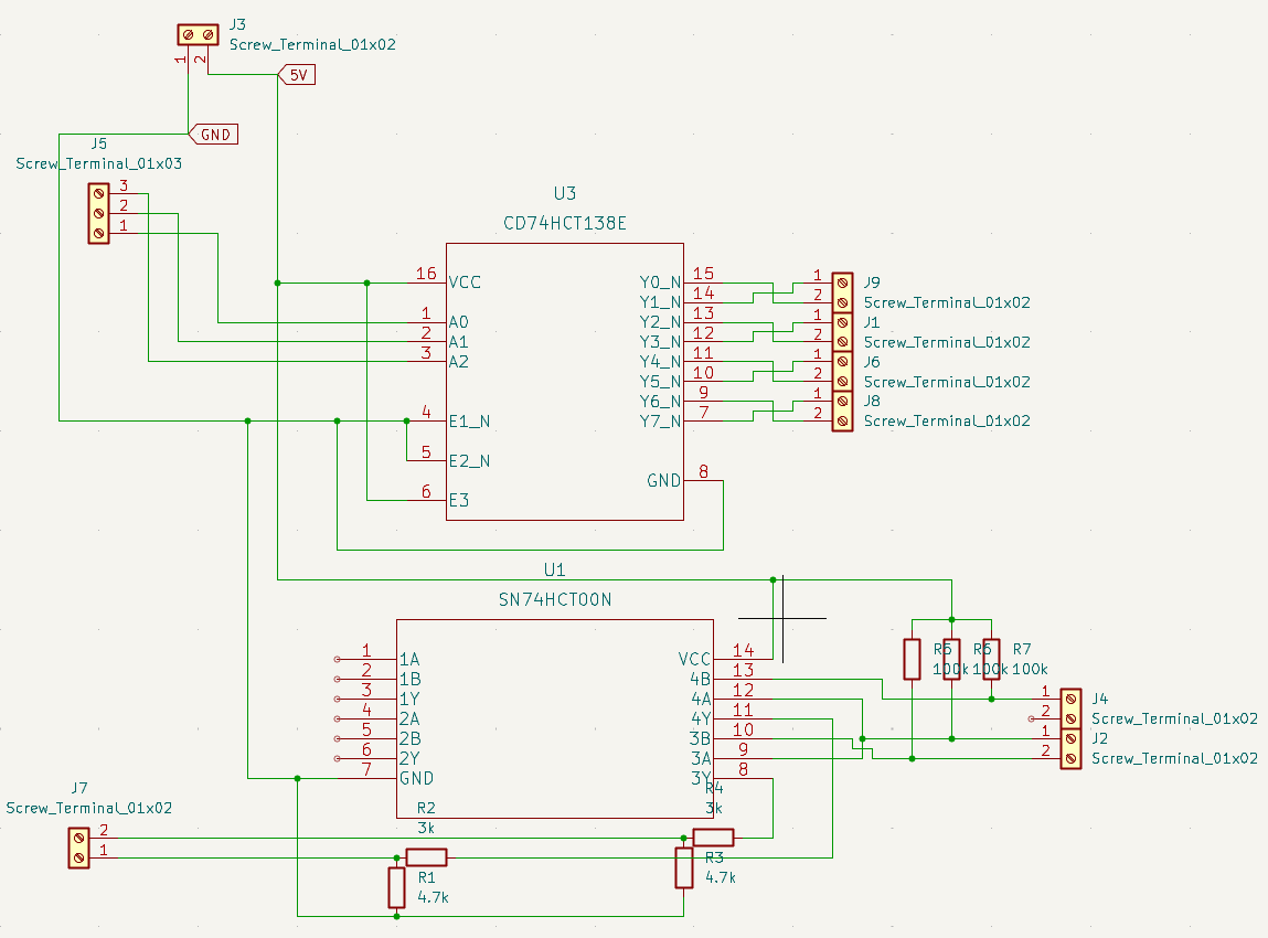
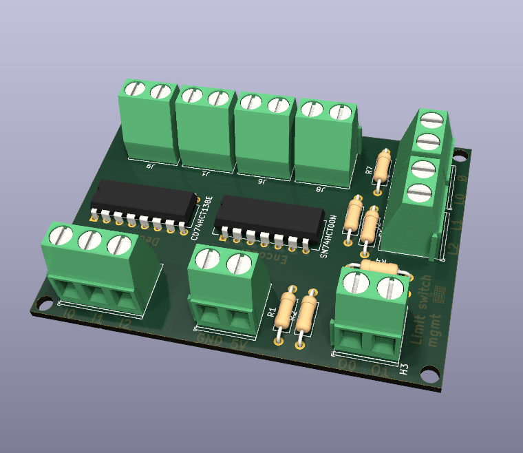
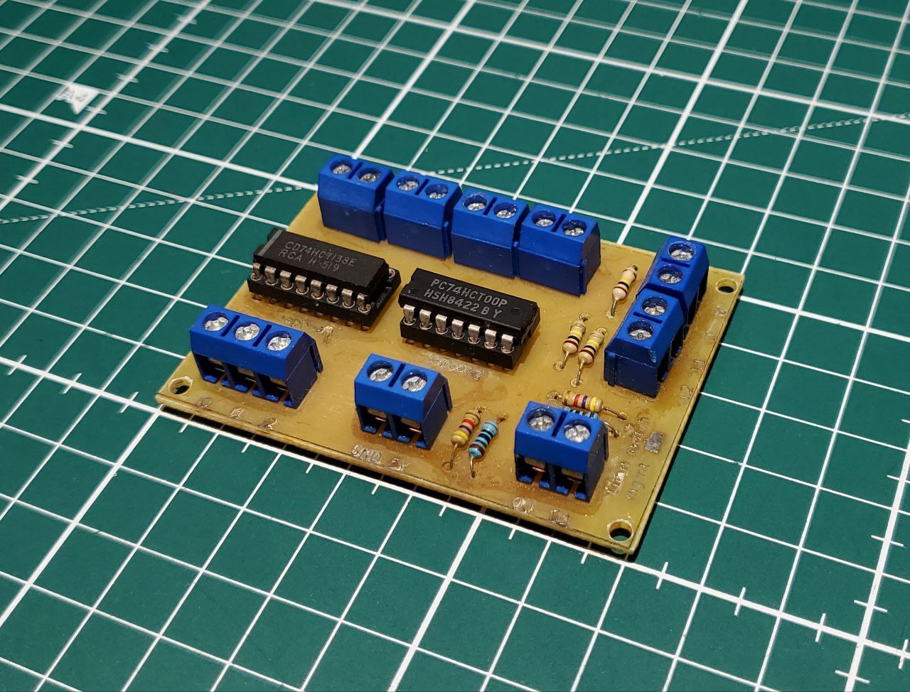
The Limit Switch Management Board was responsible for controlling the matrix of limit switches located at the base of the robot. Comprising 21 interconnected switches arranged in a 3x7 matrix, it operates similarly to a keyboard matrix. This board was designed to support essential functionalities, including system recalibration, detecting the presence of an object precisely where it needs to be manipulated, and triggering an emergency stop in case of unexpected contact. Its implementation enhances the robot's precision, safety, and adaptability to dynamic environments.
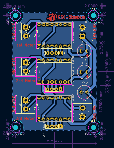
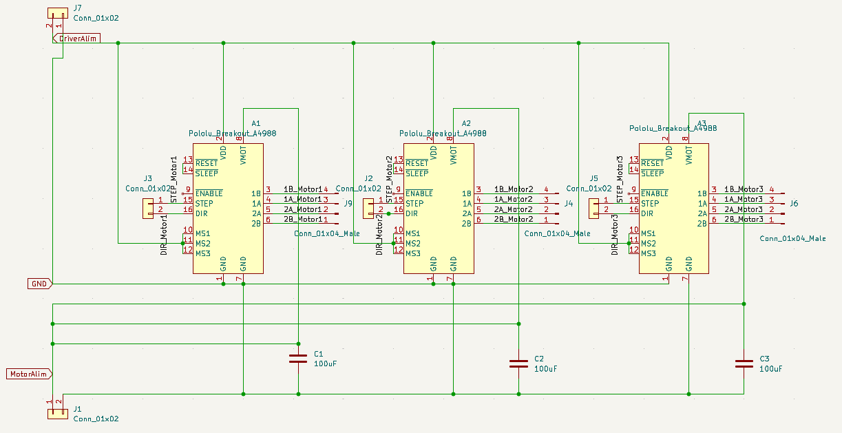
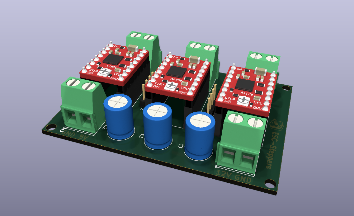
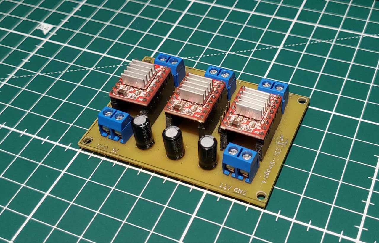
The Stepper Driver Board integrates A4988 drivers to control the three 59 Ncm NEMA 17 stepper motors. This board acts as the interface between the microcontroller and the motors. It serves as the critical interface between the microcontroller and the motors, translating the PWM control signals from the microcontroller into the necessary power to drive the motors efficiently.
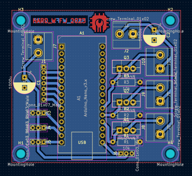
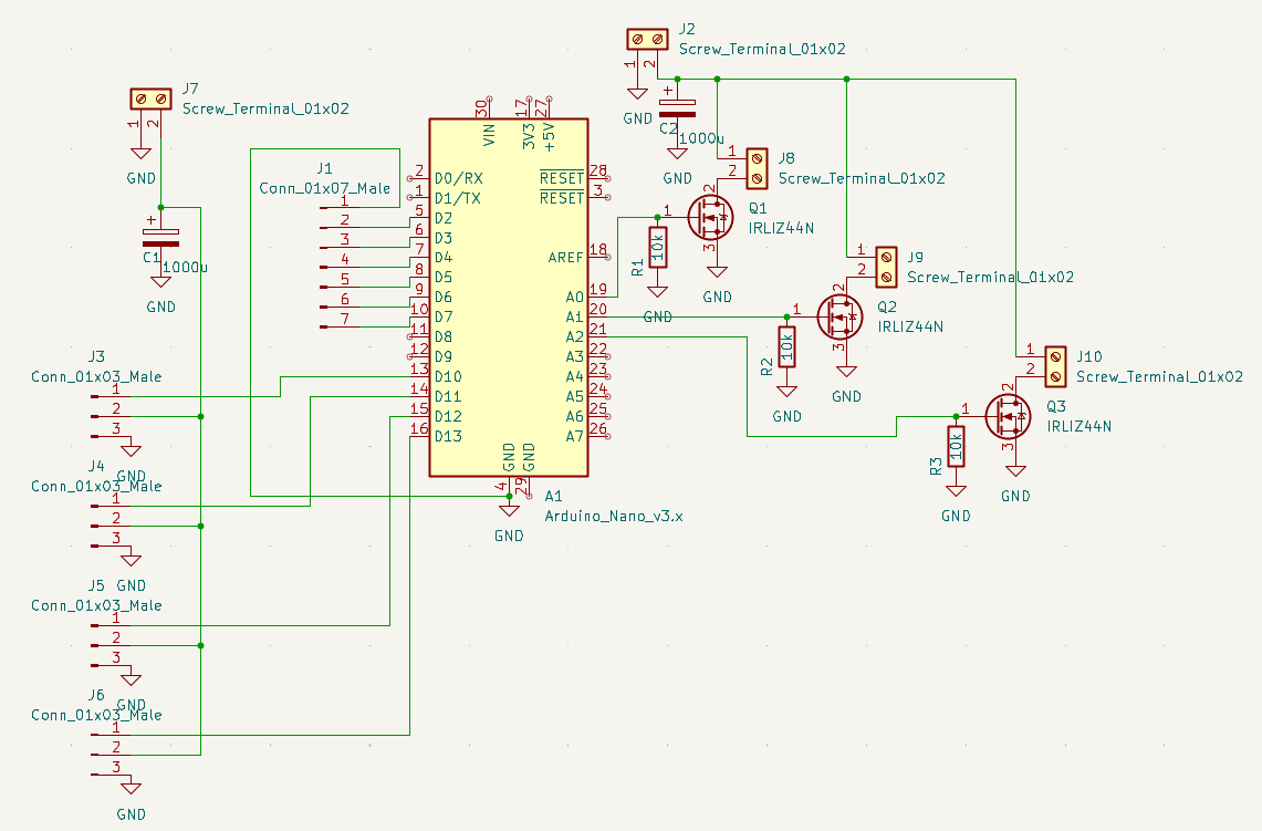
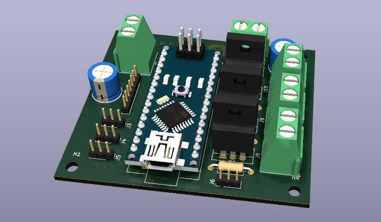
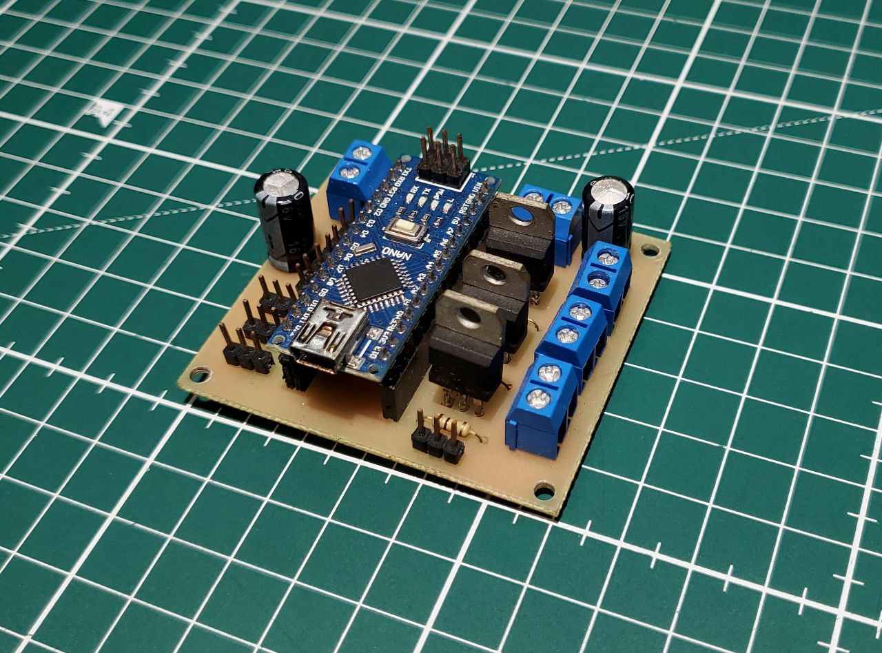
The Micro Controller Board integrates the Arduino Nano V3 and acts as the central hub for controlling various components of the robot. It manages the operation of actuator servo motors, as well as the LED strips. Additionally, this board handles the commands sent to the stepper driver board.
Micro Controller and Rosserial
Communication between the Arduino Nano V3 and the robot's central processing unit, the Raspberry Pi 3B+, is facilitated via USB using the rosserial protocol. In this configuration, the Arduino serves as the client, while the Raspberry Pi functions as the server. This setup enables the transmission of motor control commands from the Raspberry Pi to the Arduino, which then generates the appropriate PWM signals to control the motors.
The use of rosserial allows for efficient communication and data exchange between the two devices. This system architecture enables seamless operation of the robot, with the Raspberry Pi handling complex computations and decision-making, while the Arduino executes low-level control tasks, such as motor control.

ROS (Robot Operating System)

HARP1 operated under ROS1 Melodic, incorporating the YDlidar-X4 2D LiDAR into its ROS architecture for environmental sensing and obstacle avoidance. A custom Python node was developed to process the lidar data from its ROS driver topic, provide velocity commands, and trigger actuators and LED strips via rosserial. This node acted as the central orchestrator, integrating and executing the robot's game strategy sequence while coordinating various hardware components. This architecture ensured efficient communication and control throughout the system.
Actuator
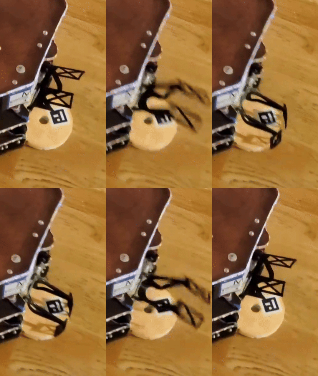
HARP1 featured three actuators, one on each side of the robot, designed as large paddles to securely hold the game elements—referred to as 'cakes'—during transport. Each actuator was powered by an SG90 9g micro servo motor, which controlled the paddle's rotation angle. These servo motors were driven by PWM signals. The actuators played a crucial role in the robot's ability to interact with and efficiently manipulate the game elements during its tasks.
 Micro-ROS
  ROS
ROS  NAV2: MPPI Parameters Tuning