Dynamixel MX Series Servomotor Configurator
Dynamixel servo motors can be controlled in different ways : by Wizard2.0 the Dynamixel software or Raspberry with pypot each requiring a USB2Dynamixel or by Raspberry or Arduino with Dynamixel shields. However, to set the fundamental parameters of the dynamixel servo, it is generally the Dynamixel software on the computer that is used. This is very restrictive and that is why I was led to develop a small embedded system to facilitate the setting of Dynamixel MX series servos.
Table of Contents
- Equipment At My Disposal
- Simple Communication With The Servo Motor
- Parameter Setting Function
- User Interface
- Implementation Of The Project
5.1 Electrical Circuit
5.2 Enclosure - Final Test
- Downloadable Resources
Equipment At My Disposal
- An Arduino Uno as motherboard
- An Arduino 2.8 TFT LCD Shield touch screen as user interface
- One MX-106 servo motor and one MX-28 servo motor for testing my project
Simple Communication With The Servo Motor
To avoid having to purchase one of the above-mentioned connectors, the choice was made to control the servo via TTL serial communication from an Arduino Uno (i.e. using the Rx and Tx ports of the Arduino). However, reverting to the motor's intrinsic communication protocol requires a good understanding of it and sending the right binary data packets. Another difficulty is that the servo data pin is a duplex for transmitted and received information. However, on the arduino the serial communication pins are separate.
A thorough review of the state of the art led me to note that a similar project had already been done on a proprietary card by JosueGutierrez from SavageElectronics. However, it is the work of Mahyar Abdeetedal that has contributed to the development of the following elements. Indeed, despite the fact that Dynamixel has developed an Arduino library in partnership with its community, it was designed for the use of Dynamixel shields and was not conclusive for the desired use. To avoid developing a new library, research led me to the work of J.Teda who created the Dynamixel_Serial library on Arduino.
Therefore, to communicate with the Dynamixel, the SN74LS241 3-state buffer is required, allowing half-duplex communication according to the following circuit:
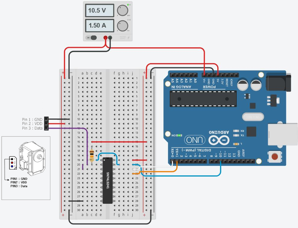
Communication circuit with the servomotor
Parameter Setting Function
Now able to communicate with the servo motor, it will be necessary to write the function to configure the servo motor whatever its current parameters.
//======Library======//

#include <Dynamixel_Serial.h>     // Library needed to control Dynamixel servo

//======Servo parameters======//

#define SERVO_ControlPin 10       // Control pin of buffer chip
#define LED13 0x0D                // Pin of Visual indication for running "heartbeat" using onboard LED

//======Variable======//

long Baud[9] = {9600, 19200, 57600, 115200, 200000, 250000, 400000, 500000, 1000000};
bool MODE = 1;                    // ServoMode by default
int Torque = 100;                 // 100% torque by default
unsigned int CWLimit = 0x000 * 0.088;  // converts the hexadecimal input to degrees
unsigned int CCWLimit = 0xFFF * 0.088;
void ResetServo(){                               // Pin setup for Visual indication of running (heart beat) program using onboard LED
  pinMode(LED13, OUTPUT);
  digitalWrite(LED13, HIGH);

  for (int b = 0; b < 9; b++){                     // This "for" loop will take about 20 Sec to complete and is used to loop through all speeds that Dynamixel can be and send reset instruction
    long Baudrate_BPS = 0;
    Baudrate_BPS  = Baud[b];
    if(Baudrate_BPS == 57600){
      Dynamixel.begin(Baudrate_BPS, SERVO_ControlPin); // Set Arduino Serial speed and control pin
      Dynamixel.reset(0xFE);                           // Broadcast to all Dynamixel IDs and reset to factory default
    }
    else{
      Dynamixel.begin(Baudrate_BPS, SERVO_ControlPin); // Set Arduino Serial speed and control pin
      for (int i = 1; i < 0xFF; i++){
        Dynamixel.reset(i);
      }
      delay(5);
    }
    delay(100);                                      // Time needed for Dynamixel to broadcast
  }
  digitalWrite(LED13, LOW);
  delay(3000);                                     // Give time for Dynamixel to reset
}
The ResetServo() function has the role of « making the servo programmable ». In fact, let's consider at the beginning that the servomotor is of unknown ID and Baudrate. In this case, it is necessary to be able to impose working parameters before imposing those desired by the user. This is what this function does by using the reset instruction, imposing 57600bps as the working frequency.
void ProgramBaudrateID(long SERVO_SET_Baudrate, int SERVO_ID, bool MODE, int Torque, unsigned int CWLimit, unsigned int CCWLimit){
  // Now that the Dynamixel is reset to factory setting we will program its Baudrate and ID

  Dynamixel.begin(57600, SERVO_ControlPin);         // Set Arduino Serial speed to factory default speed of 57600
  Dynamixel.setID(0xFE, SERVO_ID);                  // Broadcast to all Dynamixel IDs(0xFE) and set with new ID
  delay(10);                                        // Time needed for Dynamixel to set its new ID before next instruction can be sent
  Dynamixel.setStatusPaket(SERVO_ID, READ);         // Tell Dynamixel to only return status packets when a "read" instruction is sent
  delay(30);

  Dynamixel.setBaudRate(SERVO_ID, SERVO_SET_Baudrate);   // Set Dynamixel to new serial speed
  delay(30);                                             // Time needed for Dynamixel to set its new Baudrate
  Dynamixel.begin(SERVO_SET_Baudrate, SERVO_ControlPin); // We now need to set Arduino to the new Baudrate speed

  Dynamixel.ledState(SERVO_ID, ON);                      // Turn Dynamixel LED on
  delay(5);
  Dynamixel.setMode(SERVO_ID, MODE, int(CWLimit * 11.375), int(CCWLimit * 11.375));  // Set mode to SERVO, must be WHEEL if using wheel mode
  delay(30);
  Dynamixel.setMaxTorque(SERVO_ID, int(Torque * 7.67));  // Set Dynamixel to max torque limit
}
Now programmable, user parameters are applied to the servomotor : Baudrate, ID, Operating mode, torque, min and max angle.
User Interface
Now that the major function is done, the user must be able to impose its parameters. To do this, it was chosen to use the 2.8 TFT LCD Shield touch screen. The GFX library from Adafruit was used to create the graphical interface and is based on the following idea :
//======Library======//

#include <Adafruit_TFTLCD.h>
#include <Adafruit_GFX.h>
#include <TouchScreen.h>

//======GPIO======//
[...]

//======Screen Calibration======//
[...]

//======Colors======//
[...]

//======tft object declaration======//

Adafruit_TFTLCD tft(LCD_CS, LCD_CD, LCD_WR, LCD_RD, LCD_RESET);
TouchScreen ts = TouchScreen(XP, YP, XM, YM, 300);

//======Variable======//

char currentPage;
void setup() {
  // Initial LCD setup //

  tft.reset();
  tft.begin(0x9341);
  tft.setRotation(3);

  DrawHomeScreen();
  currentPage = '0';         // Indicates that we are at Home Screen
}
The setup displays the wallpaper once on switch-on after initializing it.
void loop() {
  if(currentPage == '0') {
    TSPoint p = ts.getPoint();    // Get touch point

    if (p.z > ts.pressureThreshhold) {
        p.x = map(p.x, TS_MAXX, TS_MINX, 0, 320);
        p.y = map(p.y, TS_MAXY, TS_MINY, 0, 240);

        if(p.x > 30 && p.x < 285 && p.y > 130 && p.y < 200) {    // The user has pressed inside the red rectangle
        // This is important, because the libraries are sharing pins
        pinMode(XM, OUTPUT);
        pinMode(YP, OUTPUT);
        currentPage = '1';
        DrawBaudRateSetup();
      }
    }
  }

  // [...]
}
The loop is responsible for checking at any time whether there has been an interaction on the screen by looping over « ifs » and, if necessary, displaying a new feature.
void DrawHomeScreen() {
  // Background in black //
  tft.fillScreen(BLACK);

  // Draw white frame
  tft.drawRect(0, 0, 319, 240, WHITE);

  // Print "Dynamixel" Text
  tft.setCursor(110, 30);
  tft.setTextColor(WHITE);
  tft.setTextSize(2);
  tft.print("Dynamixel");

  // Print "Configuration of MX servo" Text
  tft.setCursor(10, 50);
  tft.setTextColor(WHITE);
  tft.setTextSize(2);
  tft.print("Configuration of MX servo");

  // Create Red Button
  tft.fillRect(30, 130, 260, 70, DRED);
  tft.drawRect(30, 130, 260, 70, WHITE);
  tft.setCursor(118, 138);
  tft.setTextColor(WHITE);
  tft.setTextSize(3);
  tft.print("Start");
  tft.setCursor(40, 168);
  tft.setTextColor(WHITE);
  tft.setTextSize(3);
  tft.print("configuration!");
}
To draw, loop and setup independent functions are created for each page being displayed that need to be called at the desired time as shown above.
Implementation Of The Project
Almost finished, it is only a question of making the electrical circuit and its box.
Electrical Circuit
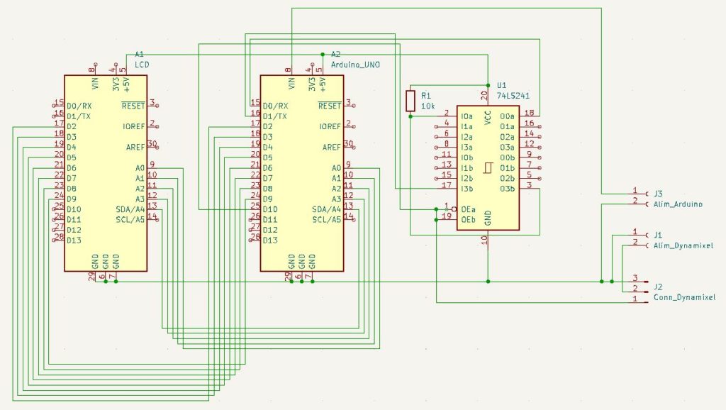
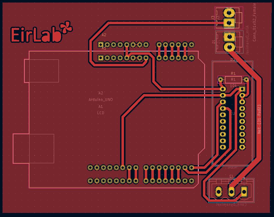
Electronic schematic and PCB
Enclosure
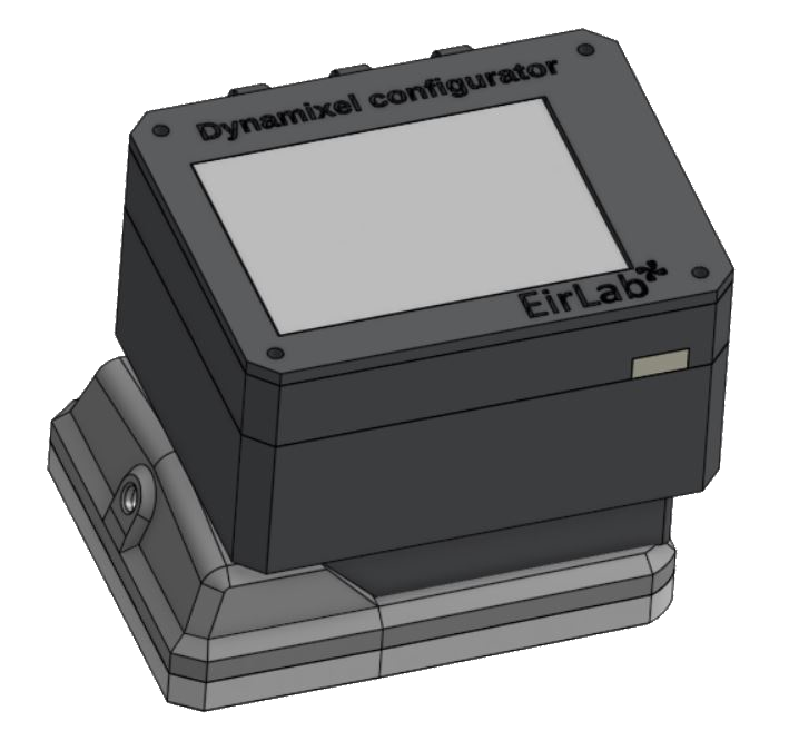
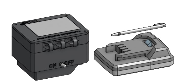
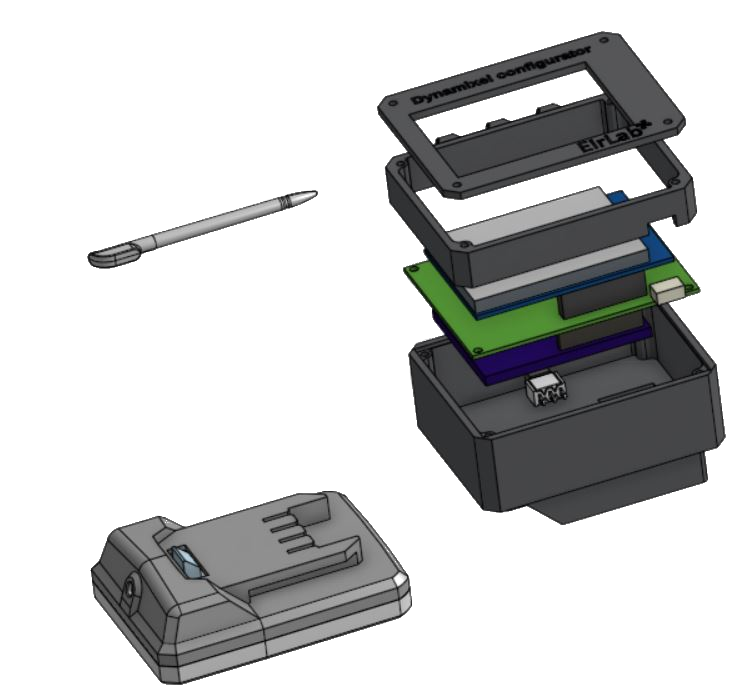
3D model
Final Test
Downloadable Resources
Full project code
Top of the enclosure made by laser cutter
Electrical circuit
3D model
This article can also be found here